Design Structure Matrix Overview
A design structure matrix (DSM) consists of two parts
- A matrix to visualize dependencies
- Algorithms which can be applied on the matrix to discover e.g. layering in the software.
First the design of a small example software application is shown in UML. Then step-by-step it is explained how using a DSM can help to understand and improve the design.
Design in UML
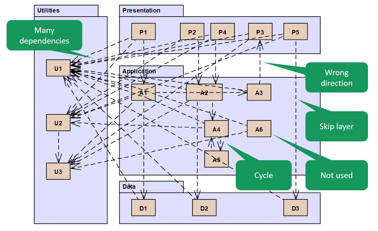
Figure 1: UML design with some design problems
The design shown above intentionally contains the some typical design errors:
- A cyclic relation between A4 and A5.
- A relation from A3 to P3 against the expected layering.
- A relationship from P5 to D3 that skips a layer.
- An unused element A6 without incoming relationships.
- A element U2 with many in- and outgoing relationships (not shown to avoid cluttering the diagram)
Showing the many relations to and from the elements U1 to U3 obfuscates the diagram. This illustrates that the widely used UML notation is not suitable for representation of large amounts of dependencies. For that reason, UML diagrams often does not show all relationships, but only the most essential, making it an incomplete representation.
Design in DSM
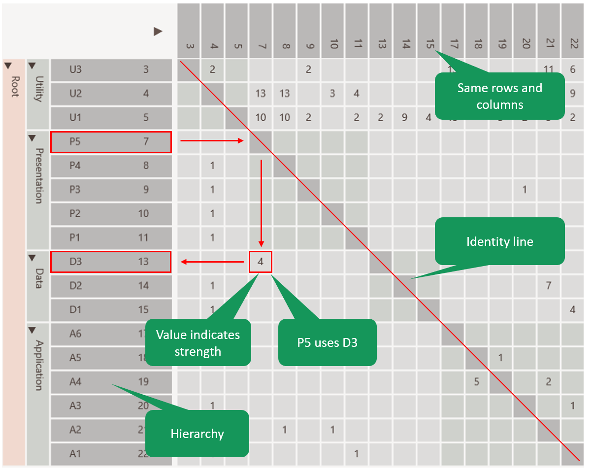
Figure 2: DSM visualization of the same design
The figure above shows the same design in a DSM.
- The DSM consists of a matrix with the same elements in the rows and columns.
- The hierarchy of packages and elements is visible on the left.
- The relations between the elements are shown in the cells.
That column 7 (P5) of row 13 (D3) is filled, for example, means that P5 is dependent on D3. This is in accordance with the UML diagram.
The number in the cell represents the strength of the relationship and is usually the number of dependencies between the elements.
The cells on the diagonal represent the relationship of an element with itself and are usually empty.
Although it takes some time to get comfortable with reading the matrices, there are a number of important advantages over UML. These key strengths are discussed below.
Key strengths
Key strength 1 - Concise
In a DSM, the hierarchy can also be folded in whole or in part. The relational strengths of the collapsed cells are simply combined. As a result, the DSM will become more compact, but will still remain correct in terms of content.
In this way it is possible to display a system with thousands of elements and still keep the overview.
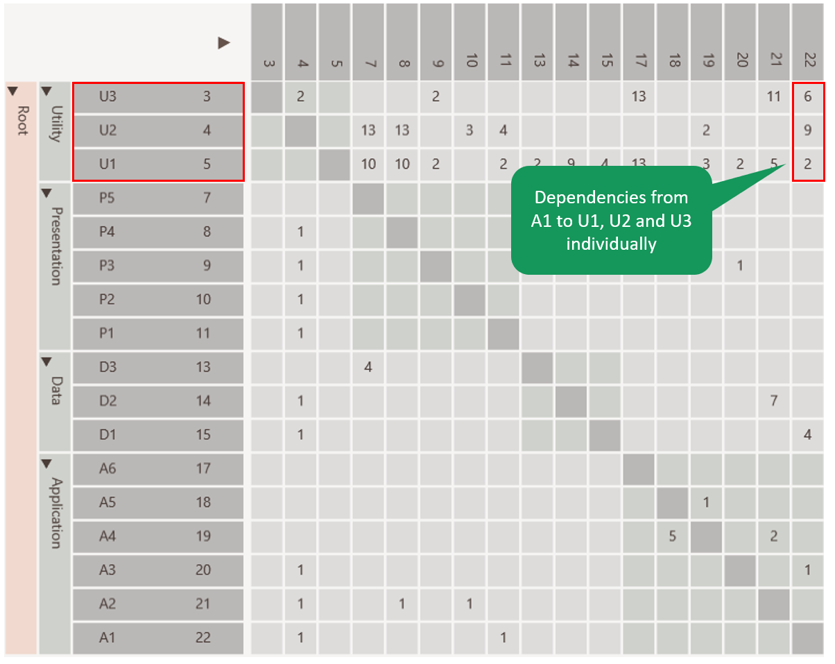
Figure 3: DSM fully expanded
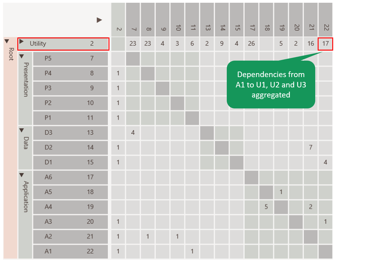
Figure 4: DSM partly collapsed

Figure 5: DSM fully collapsed
Key strength 2 - Architectural Discovery
By applying a partitioning algorithm on the DSM, the layering of the software can be discovered. Such an algorithm tries to reorder the DSM in such a way that as many relationships as possible come under the diagonal.
After partioning elements with many inbound relationships (providers) have shifted to the bottom, while the elements with many outgoing relationships (consumers) have shifted to the top.
Cyclic relations can be easily spotted, because the type of relations remain above the diagonal.

Figure 6: DSM before partioningd
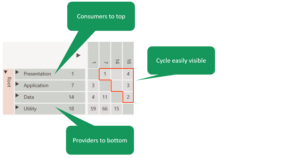
Figure 7: DSM after partioning
The figure above shows that there are problems with the layering:
- The presentation layer directly uses the data layer, thereby skipping a layer. This is caused by P5 in the presentation layer directly using D3 from the data layer.
- The application layer uses the presentation layer, which goes against the expected layering. This is caused by A3 in the application layer using P3 in the presentation layer, which is violates the expected layering.
- The utility layer uses all other layers, which goes against the expected layering. This is caused by U2 using all layers.
Key strength 3 - Dependency pattern discovery
A DSM makes it easy to recognize dependency patterns.
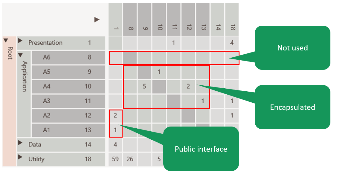
Figure 8: DSM encapsulation pattern
The DSM above shows that:
- elements A1 and A2 are the public interfaces towards the presentation layer.
- elements A3, A4 and A5 are internal elements of the application layer, because they are used inside the application layer.
- element A6 is likely an unused element.
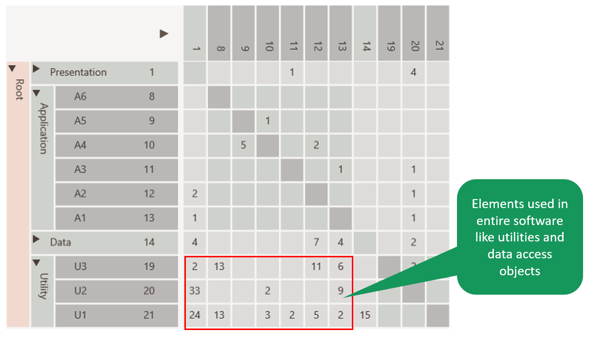
Figure 9: DSM bus pattern
The DSM above shows that elements U1, U2 and U3 are used throughout the software. This means they are a kind of utility elements.
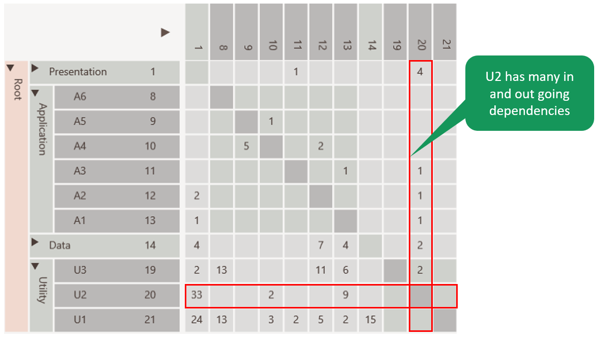
Figure 10: DSM change propagator pattern
The DSM above shows that element U2 is problematic, because in addition to incoming relationships it also has outgoing relationships. It is called a change propagator. Changing this elements has impact on many pieces of the software.
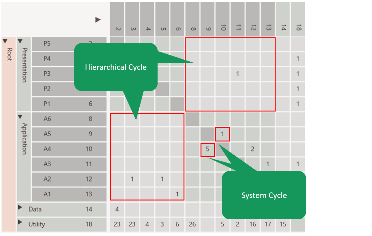
Figure 11: DSM cycle types
The DSM above shows two different types of cyclic relations. Each type requires a specific type of refactoring to remove it:
| Dependency type | Description | Required refactoring |
|---|---|---|
| System Cycle | Direct cycle between elements e.g A4 <-> A5 | Introduce interface |
| Hierarchical Cycle | Cycle between packages caused by relations between elements not being in a single direction e.g. A3->P3 combined with P2->A2 | Move element to other module |
Key strength 4 - Assist in refactoring
A DSM can be used to improve the dependency structure. One can think of:
- Removing cyclic dependencies.
- Improving the cohesiveness of a component by move elements to other component were the have stronger relations.
In the matrix we can move an element to another component or layer, combine it with other elements or split and then recalculate all dependencies to see if this yields a better dependency structure.
In our example we had a relation from A3 to P3 against the expected layering. Now suppose after inspecting the source code we discover that P3 does not contain user interface but application code.
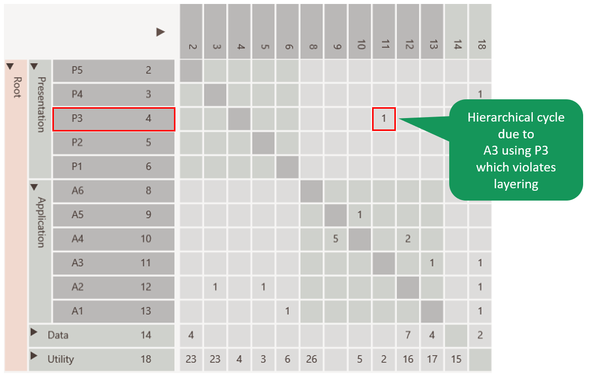
Figure 12: DSM before refactoring
Therefore we decided to move it from the presentation to the application layer.
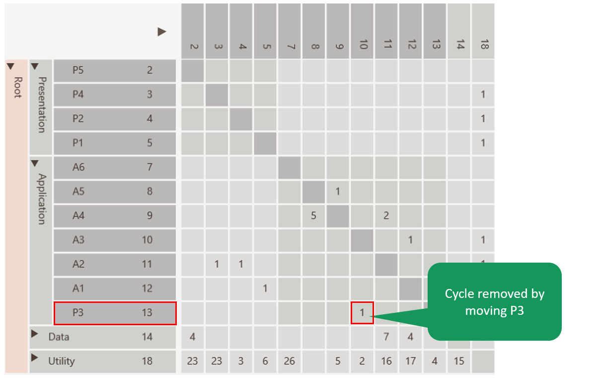
Figure 13: DSM after refactoring
After recalculating the dependencies it can be seen that the cyclical relationship between the presentation and application layer has disappeared.
The advantages of such an impact analysis are particularly evident in improvement scenarios that take place at the architectural level and thus affect multiple components. Without the use of a DSM, such analysis are unreliable, because the intended and the actual software architecture often do not match.
References
-
General information about Design Structure Matrix dsmweb.org
-
List of supporting supportings DSM visualization dsm tools
-
Technical Debt in Large Systems: Understanding the cost of software complexity presentation pdf or full report pdf
-
Achieving Agility Through Architecture Visibility Carl Hinsman, Neeraj Sangal and Judith Stafford pdf
-
Architecture migration using DSM in a large scale software project Takashi Maki, Ricoh pdf
- Well structured software is easier to maintain pdf
- Design Structure Matrix Methods and ApplicationsSteven D. Eppinger and Tyson R. Browning
